Botanical SaaS — demo pack
This page assembles sections relevant to demos and stakeholder presentations: overview, role, architecture, decisions, roadmap, and demonstration.
Contents
- Summary
- Overview
- Role and Responsibilities
- Architecture and Integrations
- Decisions, Trade-offs, and Risks
- Roadmap and Demonstration
Summary
Status
MVP / pilot run
Role
Co-founder, technical architecture owner, system designer
Stack
Java 21, Spring Boot, PostgreSQL/PostGIS, MinIO/S3-compatible storage, Angular, OpenLayers, Docker
Project value
For the target audience (botanical gardens, nurseries, plant breeders, holders of scientific collections and private plant collections):
- transition from disconnected Excel/local databases to a unified web platform;
- a unified taxonomic layer as the foundation for comparable collection data;
- managed data disclosure, public pages, and QR scenarios;
- a foundation for network exchange scenarios between organizations.
For the professional profile:
- designing and implementing SaaS from domain idea through MVP and pilot launch;
- working with multi-tenancy, RBAC, domain data model, API, GIS, AI-assisted import, public data preparation, and legislative compliance (152-FZ);
- deliberate and economical use of AI without delegating architectural decisions to the model.
What this demonstrates
This project demonstrates my ability to:
- work at the intersection of system analysis, system design, implementation, and deployment.
- take an idea through to a running system with multiple availability zones and a scaling roadmap
- strategically plan implementation of a small-to-medium-scale SaaS
- safely and in a controlled way apply LLM code generation for feature implementation
Overview
Botanical SaaS is a multi-tenant SaaS platform for botanical gardens, nurseries, plant breeders, scientific collections, and private plant collections.
The system replaces disconnected Excel files, local databases, and legacy desktop tools with a unified web platform for managing living plant collections, scientific taxonomy, geospatial data, public organization pages, QR labels, import, lists, and controlled data exchange.
My responsibility included domain modeling, backend architecture, access model design, data structure and API design, technical documentation, backend implementation, and preparing the system for cloud-ready deployment.
Role and Responsibilities
My Role
I acted as a co-founder and technical owner of the system architecture.
My work included:
- translating domain expert knowledge into a structured SaaS model;
- designing backend architecture, API, data structures, and domain model;
- implementing backend functionality and integration logic;
- designing RBAC with organization (tenant) context access rights;
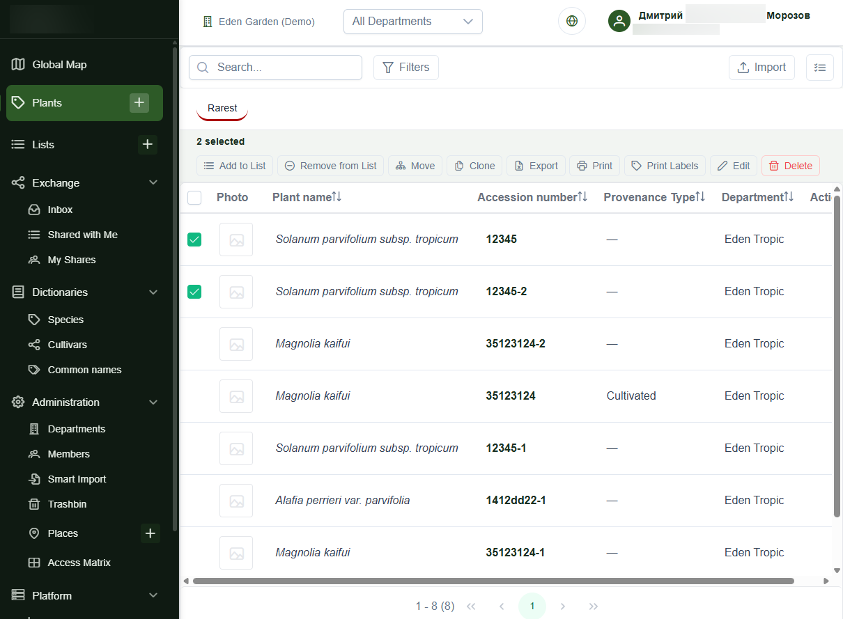
- modeling plant instances, taxonomy, places, lists, photos, imports, and public pages;
- preparing architecture documentation, C4 diagrams, and ADRs;
- aligning technical decisions with a domain expert;
- using AI-assisted development tools to accelerate routine implementation while keeping manual control over architecture, data model, API contracts, review, and deployment decisions.
AI Usage
The project was developed with AI assistance.
LLMs were used to accelerate routine implementation, generate boilerplate code, and iterate quickly. Key decisions remained under manual control:
- requirements interpretation;
- domain modeling;
- architecture decisions;
- data boundaries;
- access model;
- code review;
- debugging;
- deployment decisions;
- technical documentation.
Architecture and Integrations
Architecture
Container diagram (C4 Container)
    C4Container
    title Container Diagram for Botanical SaaS MVP

    Person(user, "User")

    System_Boundary(sys, "System") {
      Container(spa, "Single Page Application", "Angular 21, OpenLayers", "User interface")
      Container(static, "Frontend Static", "nginx", "Container for storing<br/> static frontend files")
      Container(backend, "Backend Business Logic", "Spring Boot", "Business logic")
      ContainerDb(reldb, "Relational DB", "PostgreSQL + PostGIS", "Plant instances, lists,<br/> users, RBAC roles")
      ContainerDb(objStore, "Object Storage", "MinIO", "Photos and multimedia.<br/> Collection import files")
    }

    Boundary(ext, "External systems", "") {
      Container_Ext(global, "global", "Taxonomic reference")
      Container_Ext(vernacular, "WikiData", "Vernacular names reference<br/> for plants")
      Container_Ext(llm, "LLM", "Intelligent species<br/> recognition")
    }

  Rel(user, spa, "Uses to<br/> manage plant collections")

  Rel(spa, static, "Gets Angular<br/> static UI bundles", "HTTPS")
  Rel(spa, backend, "Sends API calls", "HTTPS REST")

  Rel(backend, reldb, "Reads/writes data", "SQL")
  Rel(backend, objStore, "Uploads/reads media", "S3 API")

  Rel(backend, global, "Requests taxa/cultivars,<br/> writes cultivars", "HTTPS/REST")
  Rel(backend, vernacular, "Gets species names<br/> in national languages", "HTTPS/REST")
  Rel(backend, llm, "Uses LLM API<br/> for species name suggestions", "HTTPS/OpenAI API compatible")

  UpdateLayoutConfig($c4ShapeInRow="5", $c4BoundaryInRow="3")
Integration Flows
Taxonomy catalog import
The system includes a manual mechanism for updating the internal taxon reference from an XLS export while preserving identifiers.
National taxon name enrichment
The system includes an automatic mechanism for enriching the internal vernacular plant names reference from open sources, subject to public API constraints.
Smart Import
The platform includes an XLS import wizard for migrating existing plant collections into the system.
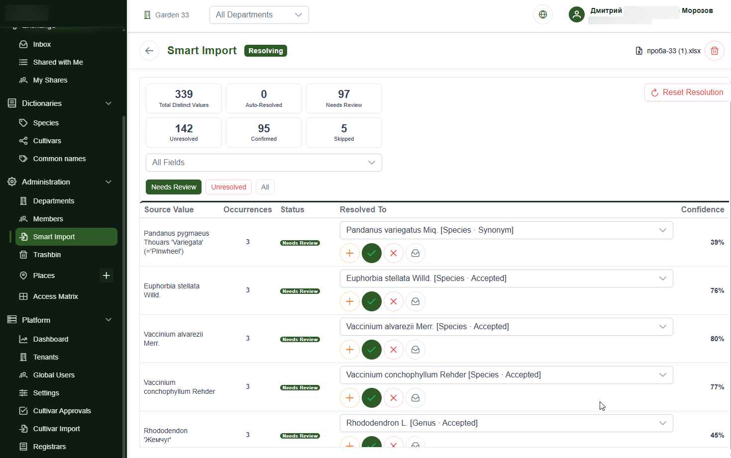
The flow supports file upload, sheet selection, column mapping (including with AI assistance), value resolution, fuzzy matching, asynchronous processing, row-level results, and Excel export of erroneous rows.
For mapping column names to system entity attributes, and for more accurate recognition of species, cultivar, or enum values, LLM integration and a lightweight harness are provided. Recognition confirmation (when it was not 100%) is performed by the user.
Decisions, Trade-offs, and Risks
Key Decisions
Decoupled frontend and backend
The system uses a separate Angular frontend and Spring Boot backend API. This reduces coupling, allows independent evolution of UI and backend logic, and creates a foundation for future client channels.
Root-unit soft multi-tenancy
Each tenant is represented by a root organizational unit. Tenant-scoped entities carry root_unit_id, and access is constrained through repositories, specifications, services, and API-level checks.
Context-aware authorization
Permissions depend not only on the user's global role, but also on the current organization and selected organizational context.
This fits B2B scenarios where the same user may have different permissions in different organizations or departments.
PostGIS as part of the domain model
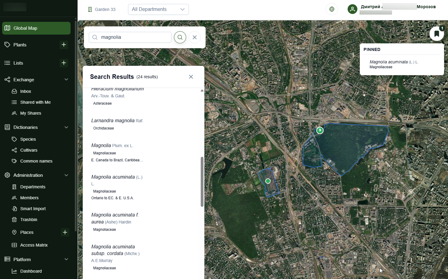
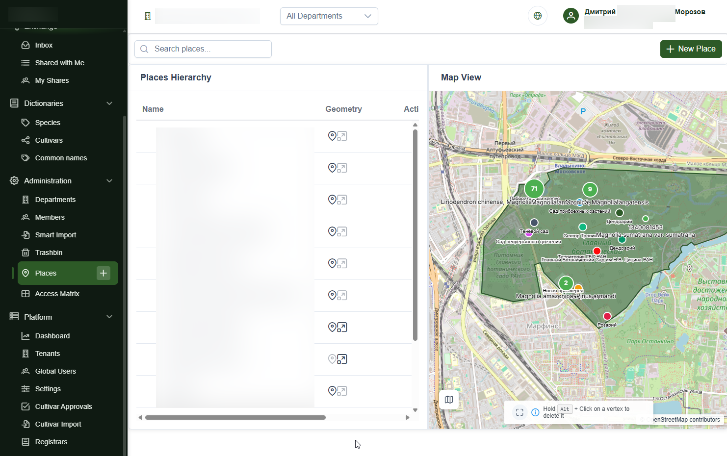
Plant locations, garden areas, greenhouses, beds, and polygons are modeled as spatial data, not as a secondary map overlay.
Hybrid current state and history model
The system separates current operational state from data related to change history and audit trail. This allows efficient work with current records while preserving traceability of important changes.
Controlled public data exposure
Public pages, plant cards, lists, photos, and map data are published through separate public endpoints and DTOs.
Visibility rules prevent accidental exposure of internal tenant data.
Architectural Trade-offs
1. Soft multi-tenancy instead of full isolation
Context
The system is designed for many organizations (multi-tenant). At an early stage the product needs low operational complexity, high development speed, and meeting functional requirements (taxonomic layer and ability to develop network scenarios between organizations).
Decision
Logical multi-tenancy through a root_unit_id attribute is used for data isolation. The root organizational unit is the organization boundary; all entities in the tree reference this root unit.
Rejected alternative
database-per-tenant or schema-per-tenant.
Rationale
- lower infrastructure complexity at an early stage
- allows absorbing organizations or spinning off departments with minimal entity migration
Trade-offs
- Data isolation is logical, not physical; any tenant filtering error in any API can break tenant isolation.
- Harder to back up, restore, export, and physically delete data for a single organization (right to be forgotten).
- Harder to dedicate a large client to separate infrastructure.
- Sharding and regional data separation will require additional design.
Compensating measures
- All entities belonging to an organization carry
root_unit_id. - Access is constrained at multiple levels: repository queries, JPA specifications, business-logic checks, controller method authorization.
- Central authorization is extracted into
AccessControlService. - Public APIs return only public DTOs and do not expose internal fields.
- Integration tests for cross-tenant access denial are written for critical scenarios.
- For 152-FZ compliance a separate availability zone for RF users is provisioned (two zones so far). Replication of public data between availability zones is planned, accounting for possible disconnection of the RF network segment from the global internet.
Review trigger
- enterprise clients requiring physical isolation
- data volume growth to noisy-neighbor levels
- need for regional data storage or legal requirement to physically separate organization data
2. Modular monolith instead of microservices
Context
The product has a broad domain model: plants, taxonomy, cultivars, lists, places, import, public pages, users, roles, media, and inter-organization exchange. The team is small and the domain model is still actively refined. It is also unclear how much load will differ across entities.
Decision
The backend is implemented as a modular monolith on Spring Boot: a single artifact with separation by domain areas through controllers, services, repositories, and DTOs.
Rejected alternative
A set of microservices: taxonomy service, collections service (+ import), media service, authorization and identity service, GIS service, public resources service.
Why this makes sense now
A monolith reduces distributed-system overhead: no network contracts between services, no distributed transactions, no service discovery infrastructure, no complex observability or inter-service failure orchestration. This speeds delivery and keeps the domain model cohesive while the product has not yet passed the first pilots.
Trade-offs
- Individual domain modules cannot be scaled independently.
- A failure in one module can affect the entire backend.
- Over time, implicit dependencies between domain areas may emerge.
- Import, media, and GIS may have different load profiles but still live in one application.
Compensating measures
- Strict package separation by domain areas. Service layer as the boundary for business logic, DTOs as the API boundary. This lowers the cost of extracting a bounded context into its own service.
- Asynchronous execution of heavy imports to avoid blocking a thread and hitting timeouts.
Review trigger
Service extraction makes sense when a specific module gets independent load scale, a dedicated owning team, a separate release cadence, or separate resilience requirements. First extraction candidates: import pipeline, media processing/storage gateway, public map/search read model.
3. Monorepo for backend and frontend instead of separate repositories
Context
The project is developed by a small team where one developer owns architecture, backend, frontend, deployment, and integration. For these conditions, speed of coordinated changes matters more than organizational independence of teams.
Decision
Backend and frontend are stored in one repository.
Rejected alternative
Separate repositories for backend, frontend, infrastructure, and documentation.
Why this makes sense now
A monorepo allows atomic API and UI changes, easier maintenance of full architectural context, faster full-stack refactoring and LLM code generation. The result is more stable because the model sees the connected product picture.
Trade-offs
- Responsibility boundaries may blur as the team grows.
- Harder to restrict access to parts of the codebase.
- Higher risk of broad changes without understanding blast radius.
Compensating measures
- Separate frontend/backend folders and independent build and run commands.
- Integration tests for frontend/backend interaction.
Review trigger
Separate repos become justified when independent teams with different release cycles appear, different code access policies, or need to publish parts of the system independently.
4. Docker Compose instead of cloud native
Context
At an early stage the system must deploy quickly on a VPS, demonstrate the product, run pilots, and keep infrastructure costs low.
Decision
Backend, frontend, PostgreSQL/PostGIS, and MinIO run in a single Docker Compose environment.
Rejected alternative
Full cloud-native infrastructure with dedicated DB and object storage capacity, container autoscaling, monitoring, and multi-zone deployment.
Why this makes sense now
Docker Compose gives fast cold start, reproducible environment, low cost, and a simple operational model. For MVP, demo stand, and early pilot this is better than premature cloud-native complexity.
Trade-offs
- A single VPS is a single point of failure.
- DB, object storage, and services compete for resources.
- Scaling is mostly vertical.
- No full high-availability model, no peak load handling. Cannot be considered production architecture.
- Backup, restore, and monitoring become critical operational tasks.
Compensating measures
- Services remain stateless.
- Configuration must be env-based.
- DB and object storage data live on persistent volumes with regular backups.
- Reverse proxy / TLS / rate limits are moved to the infrastructure layer.
- Target migration path must be described in advance: separate PostgreSQL/PostGIS instances, S3-compatible storage, horizontal scaling of service containers.
Review trigger
Transition is needed when paying clients appear, SLA expectations, growth in photo/import volume, high-availability requirements, regular VPS downtime, or need for regional data placement.
... Only part of the trade-offs is published in the portfolio.
See also Architecture Decision Records.
Roadmap and Demonstration
Roadmap
| Phase | Goal | Infrastructure | Exit criteria |
|---|---|---|---|
| MVP / demo | demonstrate a working system and core scenarios | VPS + Docker Compose | demo flow, backup, basic observability |
| Pilot | load real data and collect feedback | VPS + regular backup procedures; migrate to external S3 as media grows | import of a real collection, list of UX/data issues |
| First customers | ensure predictable operations | separate DB, external S3-compatible object storage, monitoring | paying organization, recovery procedure, support |
| Growth | prepare scaling and regional contours | separate DB, external S3-compatible object storage, separate workers (import), read optimization, regional strategy | tenant count growth, SLA expectations, regional tenant distribution |
Screenshots and Demo
Global map
Plant management
Places and boundaries management
AI-assisted plant import
What this project demonstrates
This project demonstrates my ability to:
- work at the intersection of system analysis, backend design, implementation, and deployment.
- take an idea through to a running system with multiple availability zones and a scaling roadmap
- strategically plan implementation of a small-to-medium-scale SaaS
- safely and in a controlled way apply LLM code generation for feature implementation